I do not claim to be nor do I consider myself to be an electronics expert, guru, etc. I am simply a hobbyist with no formal EE (or the like) education. If I write something completely wrong, or it is apparent that I have no idea what I am talking about, please leave a comment and set me straight. I am merely documenting my experiences and discoveries as I progress through my projects.
A buddy of mine, Jeremy, asked me the other day if I could help him out with a multiplexer/de-multiplexer chip he purchased. He was having some issues with it and couldn't quite get the results he expected. Below are some of the details on how I got this chip to work.
First off, the chip is an HEF4051B by Philips. It is an 8 channel, 3-bit chip. It's simply meant as a way to control 8 I/O pins, one at a time, while only using 3-4 I/O pins on your microcontroller. I'm sure there are other really good reasons for the chip (I believe it might double as an ADC, but I'm not sure?), but that's the most apparent one at this point.
Jeremy is using this chip as part of a larger DIY pinball machine project. Hopefully he will post some more info about the machine on his blog. If I recall correctly, the LED panels (no, not LCD) he's creating for score keeping and such will be composed of around 8,000+ surface mount LEDs!
"What is he using this chip for in his pinball machine?", you may be asking. Well, it's definitely not to control the LEDs :P It's actually to control various inputs. It will be responsible for detecting inputs from the flippers, drop targets, etc.
So how does this chip actually get used? Well, as stated above, this chip connects to four pins on your microcontroller. Jeremy and I both just happen to be using the Parallax Propeller microcontroller (I have a whole series of blog posts I need to make on this microcontroller. I won't get into it here.). The Propeller has 32 I/O pins. If we connect 8 of these mux chips to the Propeller, we can effectively double the number of I/O pins on the microcontroller for just around $3 (there are many reasons for doing it this way, of which costs is probably the least important).
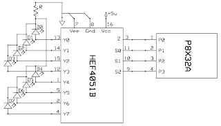
So this is a very simple schematic I whipped up in about 2 minutes. It shows how to connect the mux chip to the Propeller in order to run 8 LEDs on 4 microcontroller pins. I know, we aren't supposed to be running LEDs, we are supposed to be reading in switches. I just did it this way first, so I figured I'd post the schematic for it.

(P8X32A is the Propeller chip)
So how do we tell the mux chip which LED to turn on just by using 4 digital pins on the Propeller? Well, to be fair we only really use 3 pins when doing output (like we are doing right now). We use four pins to do input (when we use switches).
Okay, so from the schematic you will notice there are 7 I/O pins, labeled Y0 through Y7. To turn on the LED on pin Y5, we need to send "5" to the mux chip. We can't do that on just one pin, so we have to do it with the 3 pins (S0, S1 and S2 on the mux chip; P1, P2, and P3 on the Propeller). You have probably figured out by now how we do that. If not, here goes:
5 in binary is 101.
101 on the Propeller would be P1 = 1, P2 = 0, P3 = 1
We also have to set the Z pin on the mux chip to a high output (this is what the mux chip requires in order to do outputs to LEDs).
Here's the Spin code (Propeller programming language) I used:
CON
_clkmode = xtal1 + pll16x
_xinfreq = 5_000_000

mZ    = 15 'common input/output
mS0   = 11 'select input
mS1   = 10 'select input
mS2   = 9  'select input

enabledLed = 0


PUB main
dira[enabledLed]~~
outa[enabledLed] := 1

dira[mZ]~~
outa[mZ] := 1

dira[mS0]~~         'set to output
dira[mS1]~~         'set to output
dira[mS2]~~         'set to output

outa[mS0] := 1
outa[mS1] := 0
outa[mS2] := 1

repeat
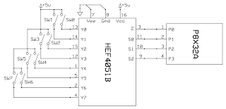
Simple enough. Now, this is the schematic for doing the input with switches.

So really it's just about the same. We just have 5v switches that ground to Y0 through Y7 on the mux chip. So now all we have to do is read the value from the mux chip when a switch is pressed.
I originally though this part would be easy since the LED part was so easy. All I have to do is press a switch then read S0, S1 and S2 to get a binary value, right? Wrong! It doesn't work that way.
Let's say we want to check if switch #7 (Y7; it's actually the 8th switch) is pressed. We have to set S0..S2 to 111 (or 7), then read from Z to see if it's high or low (in this case, high is any voltage, low is 0 volts). This tells the mux chip you are interested in Y7, then the mux chip sets Z to the voltage coming in to Y7 through the switch, which can then be interpreted by the Propeller chip. Obviously we have to iterate over all 8 switches and check them individually, but that's okay -- we can do it really fast!
Here's some code:
CONSo I'm not actually iterating over all the switches, but you can change the code to do that if you want. All I'm doing is checking to see if the switch on Y7 is pressed. If it is, then I turn on an LED. If it isn't pressed, I turn off the LED. Very simple example, but it proves the concept. The main thing to not here is that the pin referenced by "mZ" has been set as an input rather than a high output. This allows us to read the pin after the mux chip sets it.
_clkmode = xtal1 + pll16x
_xinfreq = 5_000_000
mZ = 15 'common input/output
mS0 = 11 'select input
mS1 = 10 'select input
mS2 = 9 'select input
enabledLed = 0
PUB main
dira[enabledLed]~~
dira[mZ]~
dira[mS0]~~ 'set to output
dira[mS1]~~ 'set to output
dira[mS2]~~ 'set to output
repeat
outa[mS0] := 1
outa[mS1] := 1
outa[mS2] := 1
if(ina[mZ] == 1)
outa[enabledLed] := 1
else
outa[enabledLed] := 0
Please post comments if you have any questions.


